A stair enclosure is easy to treat as leftover circulation space. That is a costly shortcut: people negotiate treads, landings, handrails, doors, direction changes, and sometimes smoke or a failed normal-power system there. The lighting package has to keep that path legible without creating bright fixtures in the line of sight, dark pockets at landings, or sensor behavior that leaves a person approaching a flight in low light.
This is a commercial-stairwell specification workflow, not a substitute for the code adopted by the project jurisdiction or for the authority having jurisdiction (AHJ). Confirm the occupancy, whether the stair is part of the required means of egress, the adopted building/fire/energy codes, and the emergency-power design before releasing a fixture schedule.
Establish the egress basis before selecting a fixture
Start with the floor plan, not a product family. Mark every flight, intermediate landing, door swing, handrail, level-of-discharge connection, exit sign, change in travel direction, and location where a person enters from a darker corridor or vestibule. Record whether the stair is enclosed, open, interior, exterior, normally locked, or used for routine travel as well as evacuation. Those conditions affect the calculation grid, aiming, controls, and service access.
For a useful submittal, ask for the exact luminaire output, optic, mounting height, and a calculation plane at the walking surface—not a generic statement that the fixture is “for stairwells.” The 2024 International Building Code (IBC) model-code text calls for at least 1 footcandle (11 lux) at the walking surface for means of egress under normal power, and raises that to 10 footcandles (108 lux) along exit access and exit stairways and their required landings while the stairway is in use. The applicable local code may use a different edition or amendments, so the design professional and AHJ must set the controlling requirement. 2024 IBC, Chapter 10
Do not use an average alone to hide a dark tread or landing. Review point values along the full run, at the first and last tread, near the door threshold, and around any turn. Also inspect vertical brightness: a glare source near eye level can make a handrail, nosing, or door hardware harder to see even when a meter records sufficient horizontal illumination.
Separate normal illumination from emergency illumination
The normal-lighting layout and emergency system work together, but they are not interchangeable. An occupancy-controlled architectural luminaire may provide the normal scene; emergency unit equipment, an integral emergency driver, an inverter, or generator-backed fixtures may provide the required failure mode. Show those circuits and the transfer behavior on the drawings so a reviewer can tell what remains illuminated after normal power fails.
For many buildings, the 2024 IBC identifies interior exit access stairways, interior and exterior exit stairways, and their associated egress areas among the locations that must be automatically illuminated when normal power fails. It specifies emergency power for at least 90 minutes and an initial average of 1 footcandle (11 lux), with a 0.1 footcandle (1 lux) minimum at floor level along the egress path; it also sets end-of-duration and uniformity provisions. Those are model-code values, not a license to skip the adopted code, electrical design, fire alarm sequence, or AHJ review. 2024 IBC, Chapter 10
Coordinate exit signs as part of the route rather than as decoration above a door. OSHA says each workplace exit route must be adequately lighted so an employee with normal vision can see along it, and that direction signs are needed where travel to the exit or discharge is not immediately apparent. It also requires exit signs to remain clearly visible and regulates their illumination and lettering. OSHA exit-route maintenance guidance
The drawings should make these questions answerable:
- Which fixtures or unit equipment provide normal stair illumination?
- Which equipment remains on after loss of normal power, and for how long under the adopted code?
- How do exit signs, emergency heads, and any remote heads preserve wayfinding at every landing and discharge?
- Does a fire-alarm, generator, inverter, or local battery test change the normal control scene as intended?
Design for treads, faces, and transitions—not a bright ceiling
A luminaire above the center of a landing can look adequate while leaving the run uneven. Use the manufacturer’s photometry to model the actual mounting geometry. Wall-mounted luminaires can put useful light on treads and walls in a narrow enclosure; continuous or segmented linear luminaires can distribute light along a run; ceiling fixtures can be appropriate where the ceiling height and photometry support the calculation. The choice is architectural, but the performance evidence must be product-specific.
Avoid direct view of a high-luminance source at the eye position of someone ascending or descending. Coordinate fixture locations with handrails, door frames, signage, cameras, sprinklers, and conduit so none blocks the intended distribution or becomes an impact/service problem. Where one side is glazed or open to an atrium, evaluate the brightness difference and reflected glare at both directions of travel.
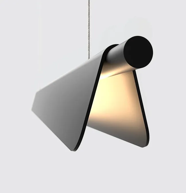
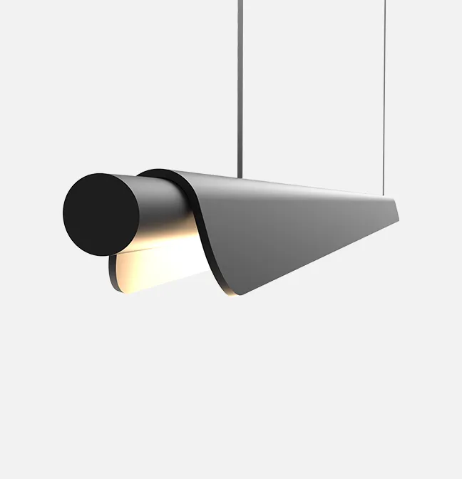
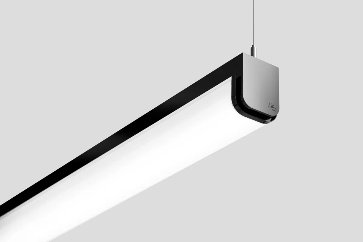
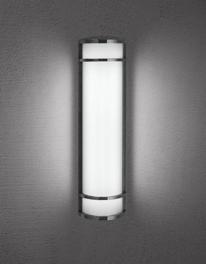
Use the linear-light category to start a shortlist for continuous wall or ceiling runs, and the wall-sconce category for wall-mounted patterns. Confirm each selected product’s location listing, mounting instructions, driver accessibility, and published photometry. For the failure mode, begin with the emergency and exit-lighting category, then verify the exact emergency configuration and compatibility in the manufacturer’s current documentation.
Make controls reduce energy without degrading safe travel
Stairwells are often intermittent spaces, which makes occupancy response attractive. But a control narrative should describe the minimum state, fade, timeout, overlap between sensor zones, manual override, test condition, and emergency behavior—not merely say “occupancy sensor.” A person should not step into an unlit flight because a sensor has no view around a door or landing.
DOE’s lighting-controls guidance explains that occupancy sensors reduce or turn off lighting when spaces are unoccupied, and its code-compliance resource notes that automatic full-power turn-on is permitted in public corridors and stairwells where manual-on operation could be unsafe. The adopted energy code still controls the actual sequence and allowable exceptions. DOE occupancy-sensor applications guide DOE lighting development and compliance guide
Coordinate the sensor layout with the field of view at each door and turn. During commissioning, walk into the enclosure at normal speed, pause on the landing, open each door, and descend from the upper floor. Test the scene at the end of the timeout as well as immediately after activation. Keep emergency illumination independent of an energy-saving timeout unless the approved life-safety design expressly provides otherwise.
Commission and maintain the whole route
Field verification is where a stairwell design becomes dependable. Before closeout, verify the installed model, lumen package, optic, mounting height, circuiting, emergency source, sensor coverage, aiming, and exit-sign visibility against the approved submittal. Meter the agreed calculation points under normal and emergency conditions where the project’s test procedure permits it. Record the results, final sensor settings, test instructions, and replacement part numbers.
Maintenance is not an afterthought. OSHA says exit routes must be kept free and unobstructed, and advises employers to test backup and safety systems such as emergency lighting regularly and repair them as needed. OSHA emergency-preparedness guidance Treat a failed driver, obscured sign, dirty lens, damaged sensor, or blocked landing as a route-safety issue—not simply a lighting-service ticket.
Stairwell lighting submittal checklist
Before approval, confirm that the package includes:
- A photometric plan with the fixture’s exact output, optic, mounting height, treads, landings, and door thresholds.
- A clear normal-power and emergency-power circuit narrative, including the adopted-code duration and test method.
- Product documentation for the selected emergency driver, inverter, unit equipment, or generator connection—not a generic emergency option.
- A control sequence with sensor coverage, minimum/maximum states, timeouts, overrides, and emergency operation.
- Exit-sign locations and wayfinding reviewed from each approach and landing.
- A commissioning record and a maintenance/testing owner after handover.
The strongest stairwell schedule does not try to solve life safety with a brighter fixture. It joins a verified walking-surface calculation, a code-coordinated emergency system, readable wayfinding, and controls tested by walking the actual route.