Data-center lighting should be designed around the installed room, not around a generic office grid. Technicians need to read rack labels, identify ports and indicators, operate at work surfaces, move equipment, and find a safe exit during an outage or alarm. Meanwhile, fixture placement, service access, and control behavior must coexist with rack rows, hot- and cold-aisle containment, cable pathways, cooling equipment, security rules, and a facility that may operate at every hour. Start with the operator’s rack plan and operating procedures, then turn them into a documented lighting and life-safety scope.
Begin with the operating room, not an average floor calculation
Identify the spaces separately: white space, network rooms, staging areas, electrical and UPS rooms, battery rooms, loading or receiving, security vestibules, offices, and egress paths. They do not necessarily have the same visual tasks, access permissions, environmental conditions, or controls. Record the intended rack orientation, aisle widths, overhead pathways, containment type, movable equipment, normal staffing pattern, and whether operators work on the front, rear, or both sides of a rack.
Build calculations around the work that will actually occur. Include the rack faces and equipment labels, aisle routes, worktables, doors, service clearances, exits, and the final mounting configuration. Name the selected luminaire output, distribution, lens, mounting, control setting, workplanes, surface reflectances, obstructions, and maintenance assumptions. A family brochure or a single average horizontal value cannot demonstrate useful visibility at a rack face or a clear route around installed equipment.
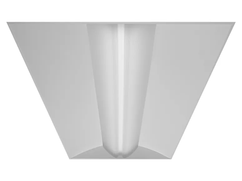
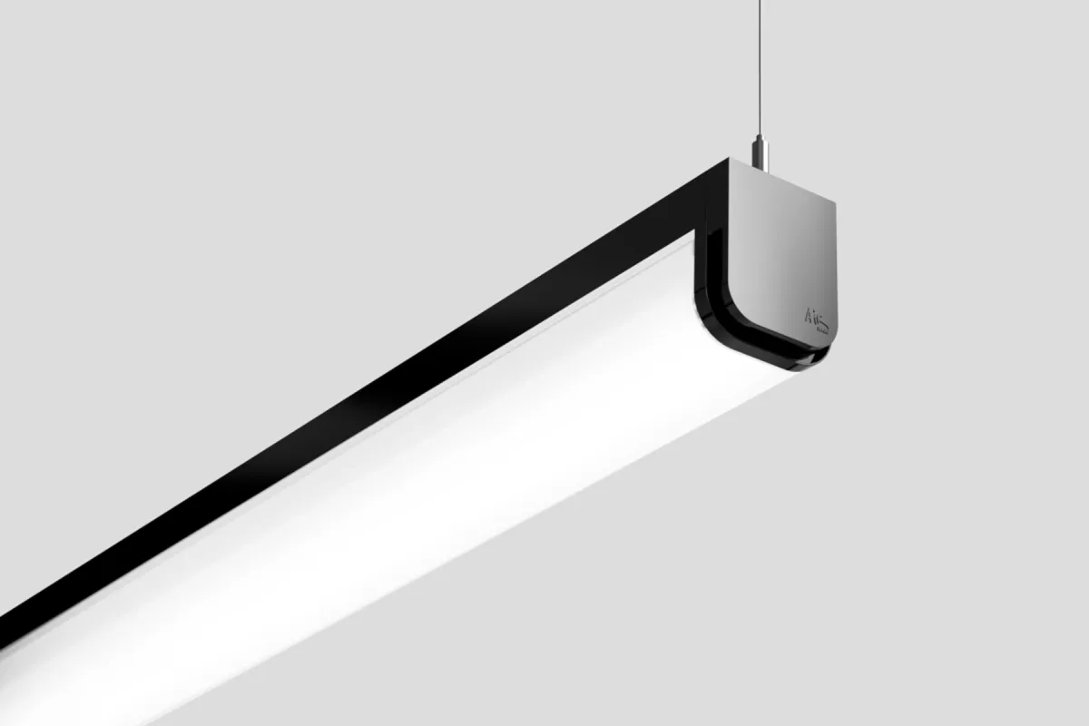
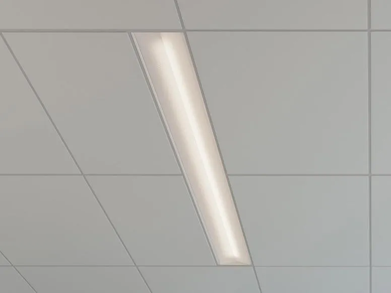
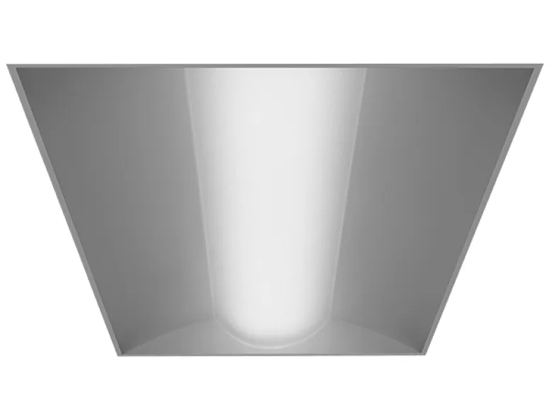
Troffers, LED panel lights, and linear lights are useful families to investigate where their published construction and mounting suit the ceiling. They are not a substitute for an air-management review, a photometric calculation, or approval of the actual installation condition.
Put light over the aisles and coordinate it with air management
The ceiling plan must be coordinated with the data-center mechanical and electrical design before a fixture family is scheduled. A recessed housing, suspension point, access panel, sensor, or conduit route can conflict with containment panels, cable tray, a return-air path, a fire-protection device, or service access. Conversely, a late change to an aisle, rack row, or containment roof can leave a light aimed at the wrong task surface.
The U.S. Department of Energy’s Federal Energy Management Program (FEMP) documented a data-center lighting retrofit measure that repositioned fixtures from above racks to above aisles, reduced lighting, and used occupancy sensors with multiple circuits for large areas. Its same case study treats air management as a coordinated system: it recommends locating perforated floor tiles only in cold aisles, containing hot air, and sealing openings around racks and floor-mounted electrical panels. Use that evidence as a layout prompt, not as a universal detail: verify every selected fixture location with the project’s airflow model, containment manufacturer, and facilities operator.
Do not relocate a fixture, cut a containment panel, or select a different lens simply to solve a glare complaint without returning to that coordination drawing. Confirm how drivers and emergency components will be reached, whether the service action enters a plenum or contained aisle, and whether the proposed maintenance procedure requires isolating a critical area. Record the approved access path in the closeout documentation.
Specify normal controls around real work and access states
Data centers can be sparsely occupied even when their IT load is continuous. Separate the normal lighting design into operational zones such as equipment aisles, staging or repair areas, entries, electrical rooms, and circulation. Then define the selected control behavior: occupancy response, time-out, local override, schedule, security interface, manual test method, and the behavior after a power event. A control sequence should never surprise a person performing a critical task, defeat a security procedure, or obscure a safe path to an exit.
FEMP’s case study specifically lists occupancy sensors and multiple circuits for large data-center areas as lighting-retrofit measures. That supports evaluating zoned control rather than treating the entire white space as one permanently energized zone; it does not establish a single time-out, sensor type, or code allowance for every project. Confirm the adopted energy code, owner standard, security policy, and equipment-maintenance procedure before finalizing settings.
For each control scene, include the people who will use it during commissioning. Test the room at typical low occupancy and during a simulated service call. Check rack labels, temporary work locations, doors, vertical surfaces, security cameras where relevant, and the transition between adjacent zones. Keep a record of the final settings and of who can adjust them.
Keep emergency and exit lighting independent, visible, and testable
Emergency and exit lighting is a life-safety system, not a dimmed version of the normal aisle lights. Coordinate emergency and exit lighting with the adopted building and fire code, the authority having jurisdiction, the electrical distribution design, and the site emergency plan. The product schedule should identify the selected unit type, mounting condition, power source or backup arrangement, circuiting, test method, and maintenance responsibility.
For U.S. workplaces, OSHA describes an exit route as a continuous, unobstructed path from any point in a workplace to a place of safety. It requires exit routes to be adequately lighted, exit doors to be visible and marked, and the line of sight to an exit sign to remain clear when travel direction is not apparent. It also requires safeguards such as exit lighting to remain in proper working order. Review the full OSHA requirements with the adopted code and AHJ rather than applying a product-category rule to a particular room.
Walk the completed egress route with final racks, carts, containment, doors, and signs installed. Test the intended emergency state—not only the normal scene—and check it from the actual aisle positions. OSHA also recommends regular testing and repair of backup systems such as emergency lighting and communication systems, as well as periodic review of the evacuation plan. Include those checks in facilities operations instead of leaving them only in the construction closeout binder.
Commission with the final rack plan and hand over the evidence
Before turnover, compare the installed fixture, lens, output, mounting, controls, emergency devices, and signage against the approved schedule and calculation. Review normal, unoccupied, maintenance, and emergency operation with facilities, security, IT operations, electrical, mechanical, and life-safety stakeholders. Where a control or fixture location was changed in the field, update the reflected-ceiling drawing, sequence, and maintenance record—not just a field note.
DOE’s current data-center design guidance frames efficiency as a system question spanning IT environmental conditions, air management, cooling, electrical systems, and heat recovery. That systems view is a useful commissioning discipline for lighting: the final work should show that visibility, maintainability, cooling coordination, energy controls, and egress were verified together.
Data-center lighting submittal checklist
- A plan identifying rack rows, hot and cold aisles, containment, overhead pathways, work areas, doors, exits, emergency devices, and proposed service access.
- A calculation package that names the selected luminaire configuration and evaluates rack faces, aisles, service tasks, and egress routes—not only an open floor workplane.
- A ceiling and air-management coordination record confirming fixture, sensor, driver, conduit, and access-panel locations with the mechanical, electrical, and containment design.
- A controls narrative covering zones, occupancy response, overrides, schedules, security coordination, reset behavior, and the commissioning method.
- Emergency and exit-lighting documentation covering the selected power or backup arrangement, test provisions, sign visibility, circuiting, and AHJ review.
- Closeout records with the final fixture schedule, calculations, controls settings, emergency-test results, maintenance procedure, and as-built drawings.