Emergency and exit lighting is a life-safety system, not a decorative lighting layer or a collection of battery fixtures placed after the ceiling plan is finished. The design must work when normal power is unavailable, but it must also make the intended path visible when people are moving under stress. Start with the adopted local building, fire, electrical, and life-safety codes; the occupancy; the authority having jurisdiction (AHJ); and an egress drawing that shows actual doors, stairs, level changes, discharge points, and route choices. This guide is a coordination workflow, not a substitute for a code analysis or AHJ approval.
Establish the adopted-code basis before choosing equipment
Do not start with a generic “90-minute emergency light” note and assume it resolves the project. The adopted editions, occupancy provisions, amendments, emergency-power architecture, and test requirements control. For example, an NFPA technical-meeting transcript describes the NFPA 101 Chapter 7 emergency-lighting requirement as at least 90 minutes, with initial and end-of-duration illumination criteria; the same discussion warns against substituting a vague “full luminaire output” phrase for the actual requirement. Read the applicable edition and project interpretation with the AHJ rather than copying a number from a different jurisdiction or occupancy. NFPA technical-meeting transcript
Workplace obligations may also apply. OSHA requires exit routes to be adequately lighted, exit signs to be visible and marked, and emergency safeguards including exit lighting to remain in working order. It also calls for directional signs where the way to an exit or exit discharge is not immediately apparent. Those federal workplace requirements do not replace local construction and fire-code review, but they are a useful reminder that a luminaire schedule alone does not establish an operable exit route. OSHA 29 CFR 1910.37
Create a short code matrix before design development. Record the adopted code editions, occupancy classification, AHJ contacts, required emergency duration and illumination criteria, exit-sign language or pictogram rules, signage visibility conditions, emergency-power basis, and applicable test-record requirements. Keep unresolved items visible instead of silently assigning them to a fixture family.
Draw the path people will actually use
Trace every path from normally occupied spaces to an exit discharge. Include corridors, stairs, landings, ramps, aisle intersections, cross-corridor doors, exterior discharge areas, and any place a person must choose a direction. Mark doors or passages that could be confused for an exit and identify locations where the nearest route is not obvious. OSHA specifically requires directional signs in the latter case and requires an exit sign’s line of sight to remain visible. OSHA 29 CFR 1910.37
Use a calculation or photometric review that follows the adopted requirement’s measurement locations and maintenance assumptions. A bright exit sign does not prove that the stair tread, change in level, turn, or exterior discharge is adequately illuminated. Review obstructions that will exist after fit-out: doors in the open position, shelving, signage, suspended equipment, soffits, partitions, and exterior canopies. Coordinate mounting height and aiming with the architectural sections, not only with reflected-ceiling symbols.
For exterior transitions, distinguish site lighting from the part of the discharge path that the adopted egress rules require. Wall packs or area lights can be starting points for an exterior family search, but a category page cannot demonstrate emergency operation, location suitability, or code compliance for a chosen configuration.
Separate normal lighting from the emergency function
Document what happens when normal power or normal controls fail. The solution may use unit equipment, an emergency driver in an identified luminaire, a central inverter, generator-backed circuits, or another system allowed by the adopted design. The right choice depends on the project’s electrical design and code basis; do not infer it from a product’s usual dimming or battery marketing language.
Listing and installation evidence matter. UL describes UL 924 as its Standard for Emergency Lighting and Power Equipment, with evaluation related to NFPA 101, NFPA 1, NFPA 70 Article 700, and the International Fire and Building Codes. Request documentation for the exact selected equipment and any required control function, rather than assuming that an ordinary luminaire, replacement lamp, or field combination has the necessary emergency evaluation. UL emergency-lighting testing and certification
Where an emergency driver or battery pack is proposed inside a general luminaire, verify the compatible luminaire, delivered emergency output, wiring diagram, charge indication, ambient-temperature limits, mounting orientation, access for service, and manufacturer instructions. UL notes that LED drivers with rechargeable battery packs are intended for installation in or with specifically identified certified luminaires. UL guide information for emergency LED drivers Do not substitute normal-mode lumens for documented emergency-mode performance.
Coordinate controls so they cannot defeat egress lighting
Put normal switching, occupancy sensing, daylight response, dimming, emergency transfer, and testing behavior on the controls narrative and one-line diagram. Identify which luminaires must respond to an emergency condition and how they behave during normal operation. A control sequence that is energy-efficient in ordinary use can still be wrong if it leaves a required path dark or prevents the emergency function from being tested.
Review the sequence with the electrical engineer, controls provider, commissioning authority, and AHJ. Make the field test explicit: normal power state, initiating condition, transfer or battery behavior, expected emergency output, duration, restoration, failure indication, and recordkeeping. OSHA advises employers to regularly test backup and safety systems, including emergency lighting, and repair them as needed. OSHA emergency-preparedness guidance
Select fixture types only after the function is clear
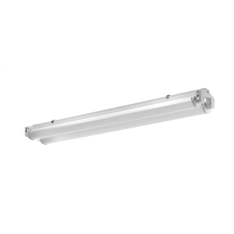
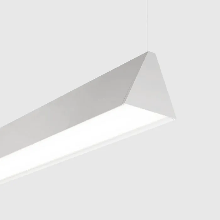
Exit signs, remote heads, combo units, dedicated emergency luminaires, and emergency-capable general lighting each solve different parts of the system. Begin with the required path and power behavior, then select equipment whose documentation matches it. Use the emergency and exit lighting category to compare published product data, and use linear lights only where their selected configuration and emergency arrangement are documented for the intended installation. Neither link is an approval of a particular product.
For every selected item, preserve the configuration-specific cut sheet, listing mark or certification evidence, photometry where relevant, emergency-mode documentation, installation instructions, compatible accessories, electrical requirements, environmental limitations, mounting details, and maintenance parts. Flag any option still dependent on a field condition, a local amendment, or a manufacturer clarification.
Emergency and exit lighting closeout checklist
- An adopted-code and AHJ matrix identifying occupancy, required egress coverage, illumination and duration criteria, sign rules, emergency source, and test obligations.
- Plans, sections, and photometric documentation that show the actual egress route, stairs, turns, doors, discharge, obstructions, and selected emergency equipment.
- A circuit and controls narrative covering normal operation, failure response, transfer or battery behavior, test method, restoration, and failure indication.
- Documentation for the exact selected configuration: listing or certification evidence, emergency-mode output, compatible luminaire or driver information, instructions, environmental limits, and service access.
- Commissioning records for the complete path, including signs, heads, emergency luminaires, transfer behavior, controls, and any required duration test.
- An owner handoff package with device locations, circuit and panel references, test records, replacement parts, inspection cadence, and the party responsible for corrective maintenance.
The objective is a traceable system: a reviewer can follow each occupied space to a discharge, see the required light and marking along the way, understand how it remains available during a failure, and find the evidence needed to test and maintain it. That is more useful than a schedule that merely labels fixtures “emergency.”