A commercial lobby is a transition between the public realm and the building’s working spaces. Its lighting has to support arrival, orientation, face-to-face reception, security, waiting, circulation, and emergency departure—often while daylight changes dramatically across a glazed façade or vestibule. Treat it as a sequence of tasks and operating states, not as one decorative ceiling. Start with the final plan, finishes, glazing, furniture, signs, and reception operations; then use a calculation, controls narrative, and commissioning record to tie the selected fixture configurations to that design intent.
Map the complete arrival sequence before selecting a statement fixture
Walk the route from the site arrival point through the exterior entrance, vestibule, security or reception desk, waiting area, lift lobby, and the first interior decision point. Mark where visitors read a sign, present identification, find a desk, use an intercom, transfer between floor finishes, or choose a corridor or elevator. Record low furniture, planters, turnstiles, display walls, artwork, glare-sensitive screens, and any high or dark ceiling planes that affect how the route reads.
The accessible route should be part of that same drawing. The U.S. Access Board’s accessible-route guidance explains that accessible routes must coincide with, or be in the same area as, circulation paths so they are not obscure or unnecessarily divergent. At a public entry, the Access Board’s entrance guidance also requires directional signs at inaccessible public entrances that point to the nearest accessible entrance. Coordinate fixture locations, feature lighting, signs, glare control, and control stations with this route; lighting cannot correct an inaccessible or confusing circulation plan after construction.
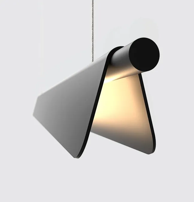
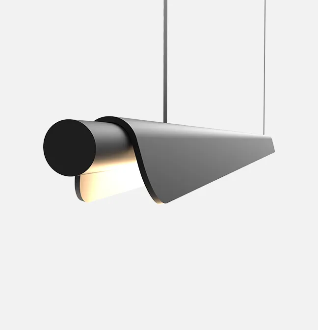
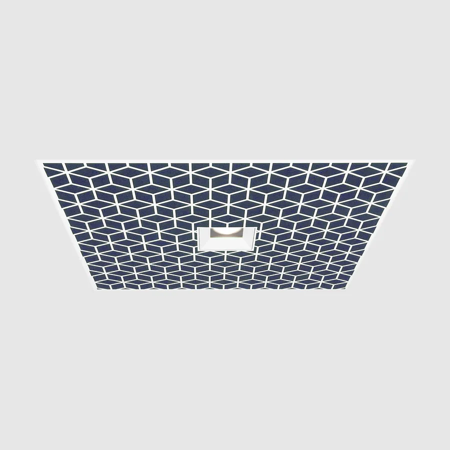
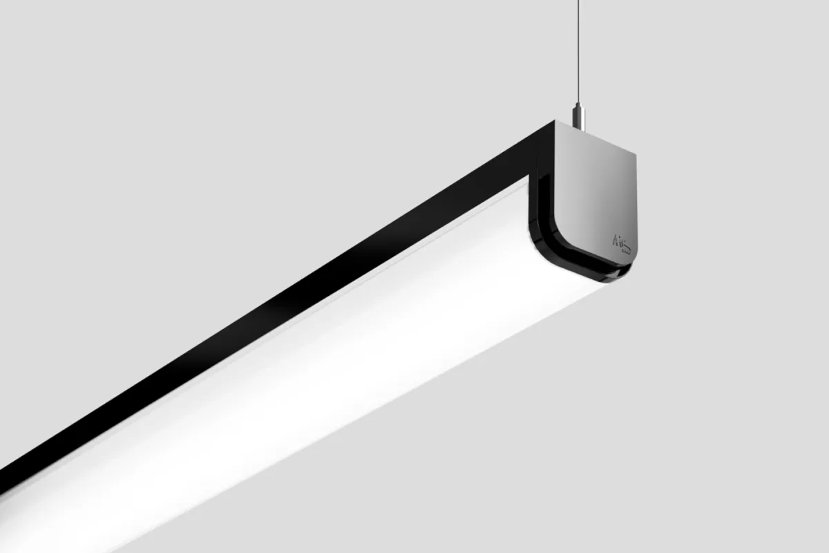
For a tall or visually prominent space, separate the lighting layers on the reflected-ceiling plan. Pendants can establish a readable arrival zone or reception scale, while linear lights can trace a circulation axis or ceiling slot. Downlights can supply a controlled ambient or accent layer, and wall sconces or cove and perimeter lighting can reveal walls, signs, and architectural surfaces. A fixture family is not a lighting solution by itself: name the selected output, distribution, finish, mounting detail, driver, and dimming configuration in the schedule and calculation.
Calculate the actual visual tasks and inspect glare in views that matter
Create calculation planes and review views for the reception work surface, sign faces, floor at transitions and doors, seating, elevator call locations, and the approach to the exit route. Include vertical surfaces where a visitor reads directory information or an employee needs to recognize a visitor’s face. Note the final reflectances, glazing, sun-control devices, desk-monitor positions, and obstructions. A single horizontal average on an empty floor does not establish that the reception task, wayfinding, or face visibility works after furniture and finishes are installed.
Review luminance and reflected glare in the likely sightlines: entering from outdoors, approaching the desk, seated in the waiting area, looking toward glazed walls, and looking from a reception monitor toward the door. Screen mockups, a temporary aiming session, and an after-dark walkthrough are often more useful than broad fixture-family claims such as “glare free.” If a feature pendant or wall-wash layer is intended to be dimmed, include its low-end behavior and scene relationship in the controls narrative rather than assuming all drivers will respond alike.
Keep the decorative layer and the task layer independently legible. A bright focal element may make a memorable arrival image but may not light a directory, a face at reception, or a safe floor transition. Conversely, an even ambient layer may not make a desk or a public route easy to understand. Record what each layer is intended to do, then test the installed scene against that purpose.
Make daylight response a designed and commissioned system
Glazed lobbies can have useful daylight and challenging contrast at the same time. The U.S. Department of Energy notes that properly integrated lighting and daylighting solutions can reduce energy use and cooling loads in commercial buildings, but the visible result depends on layout, glazing, surfaces, and control tuning—not simply on installing a photosensor. Put rows nearest a façade, skylight, or vestibule in their own documented zone where the applicable energy code and design require it; do not let a perimeter sensor unexpectedly change the entire lobby.
The DOE Building Energy Codes lighting guide explains that daylight-responsive controls use photocells and require calibration to the desired illuminance, and that sidelighted rows may need separate control because daylight declines with distance from the window. Use that principle to define the selected sensors, controlled luminaires, target scene, schedules, manual overrides, and occupancy behavior. Verify the adopted local energy code separately; the guide does not replace the project’s code path or authority having jurisdiction.
Commission the daylight scene after glazing treatments, furniture, artwork, and reception equipment are installed. Test it in representative bright and overcast conditions where practical, and confirm that a staff override returns to the documented state. Record final sensor placement, setpoints, time delays, dimming curves, and any security or building-management interface so later maintenance does not erase the original adjustment.
Coordinate reception, security, and wayfinding controls
Write operating states around people, not equipment labels: opening, normal daytime arrival, cloudy-day arrival, evening reception, cleaning, after-hours security, and emergency operation. Give facilities staff a short narrative that identifies which layer changes in each state and which functions are intentionally fixed. Do not let a decorative scene leave the reception work surface, accessible route, or wayfinding information visually ambiguous.
At secured or restricted entrances, coordinate the lighting with the communication system and the accessibility review. The Access Board notes that two-way communication systems provided for entry must include visual and audible signals to accommodate people with hearing, speech, or visual impairments. Identify the selected communication device, the receiving surface around it, control locations, and any associated signage in the architectural and electrical package. The final requirements are set by the applicable standards, code, owner program, and AHJ—not by a generic lobby detail.
Treat emergency egress as a separate life-safety system
Lobby feature lighting is never a substitute for the required emergency and exit-lighting design. OSHA states that each exit route must be adequately lighted so a person with normal vision can see along it, and that exit routes must remain free and unobstructed. Keep that requirement visible in the lobby coordination drawing: locate exit signs, emergency heads or other emergency equipment, doors, stairs, changes in direction, furnishings, and artwork that might obscure the route. The adopted building and fire codes, electrical design, and AHJ determine the required equipment, power source, testing, and photometric criteria.
Use the emergency and exit lighting schedule to identify the actual selected unit, mounting condition, circuit or power-source approach, test provision, and manufacturer documentation. Include a normal-power-loss test in commissioning with the final lobby scene, security equipment, and doors in their operating positions. OSHA’s emergency-preparedness guidance also calls for regular testing and repair of backup and safety systems, including emergency lighting; hand over a clear ownership and test-record process rather than leaving it to an unlabeled breaker panel.
Commercial lobby lighting submittal checklist
- A task and egress calculation showing the selected fixture configuration, mounting, workplanes, reflectances, obstructions, daylight assumptions, and maintenance factors.
- A reflected-ceiling and coordination plan locating luminaires, sensors, control stations, reception equipment, signs, furniture, ceiling devices, emergency equipment, and accessible circulation.
- Manufacturer documentation for the exact selected output, optic or distribution, driver, dimming protocol, finish, mounting, environmental limits, and service access.
- A controls narrative for opening, daytime, evening, cleaning, security, override, and emergency states, including daylight zones and final commissioning settings.
- A glare and wayfinding review from the entrance, reception desk, seating, elevator lobby, and exit-route approaches with final finishes and glazing considered.
- Emergency and exit-lighting cut sheets, power-source or circuiting information, test method, and a final walk-through record that confirms the route remains visible and unobstructed.