Electrical-room lighting is a maintainability and safety decision, not leftover illumination for a back-of-house room. Electricians and facilities staff need to read equipment labels, inspect terminations, operate disconnects, open doors and panels, and navigate around installed equipment. The lighting layout therefore has to protect the required working space, make controls usable during service, and coordinate with the room’s actual equipment—not simply meet an average room-level target.
Start with the equipment schedule, one-line diagram, room plan, adopted electrical and building codes, and the authority having jurisdiction (AHJ). This guide helps organize the lighting scope; it does not replace the project engineer’s code analysis, equipment manufacturer instructions, or the final AHJ interpretation.
Put equipment working spaces on the lighting plan first
Lay out panels, service equipment, switchboards, motor control centers, transformers, cable trays, doors, and required access areas before choosing a luminaire spacing pattern. In the United States, OSHA requires sufficient access and working space around electrical equipment for safe operation and maintenance. For equipment at 600 V nominal or less, its rule sets minimum working-space width and depth conditions, requires clear space from the floor to the required height, and says that required space cannot be used for storage. OSHA 29 CFR 1910.303
The lighting plan should identify the equipment working zones as design constraints. Do not locate a pendant, surface fixture, emergency head, sensor, junction box, cable tray, or other building item where it prevents a panel door from opening, interferes with equipment access, or makes future replacement harder. A reflected-ceiling plan alone rarely shows enough information: coordinate it with elevations, equipment-door swings, service clearances, and a planned equipment-removal route.
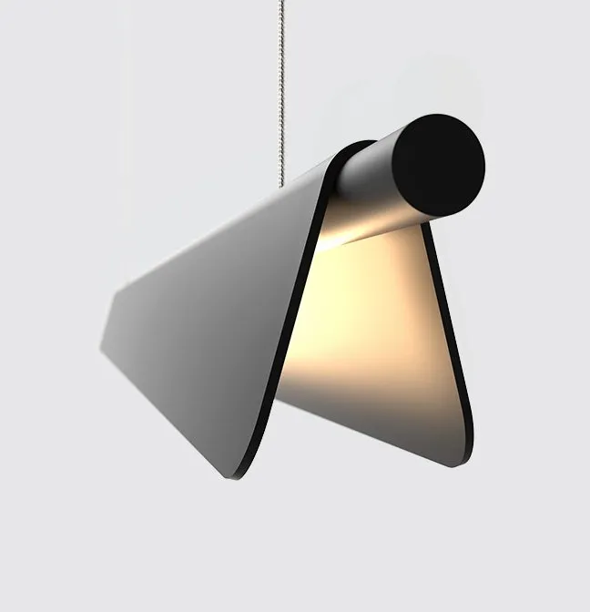
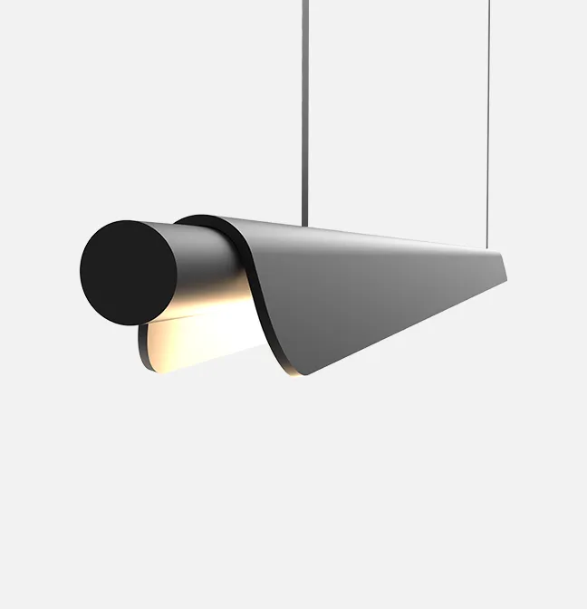
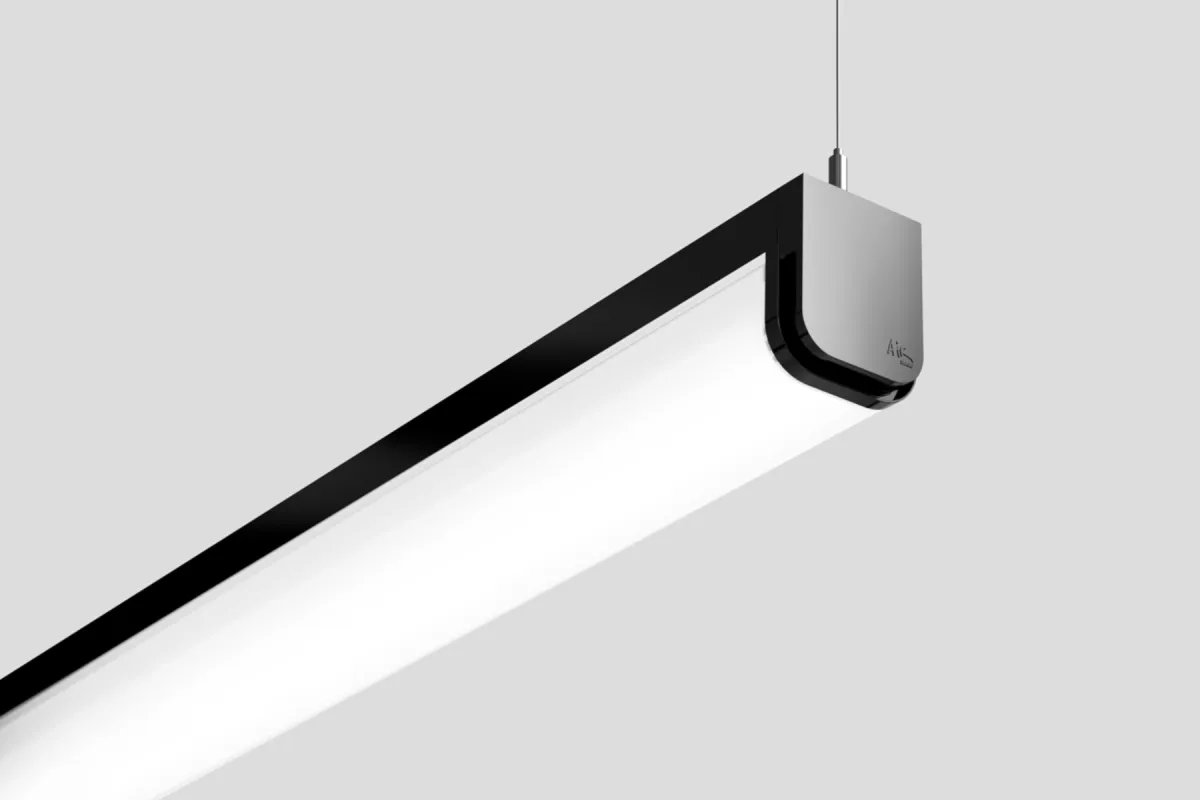
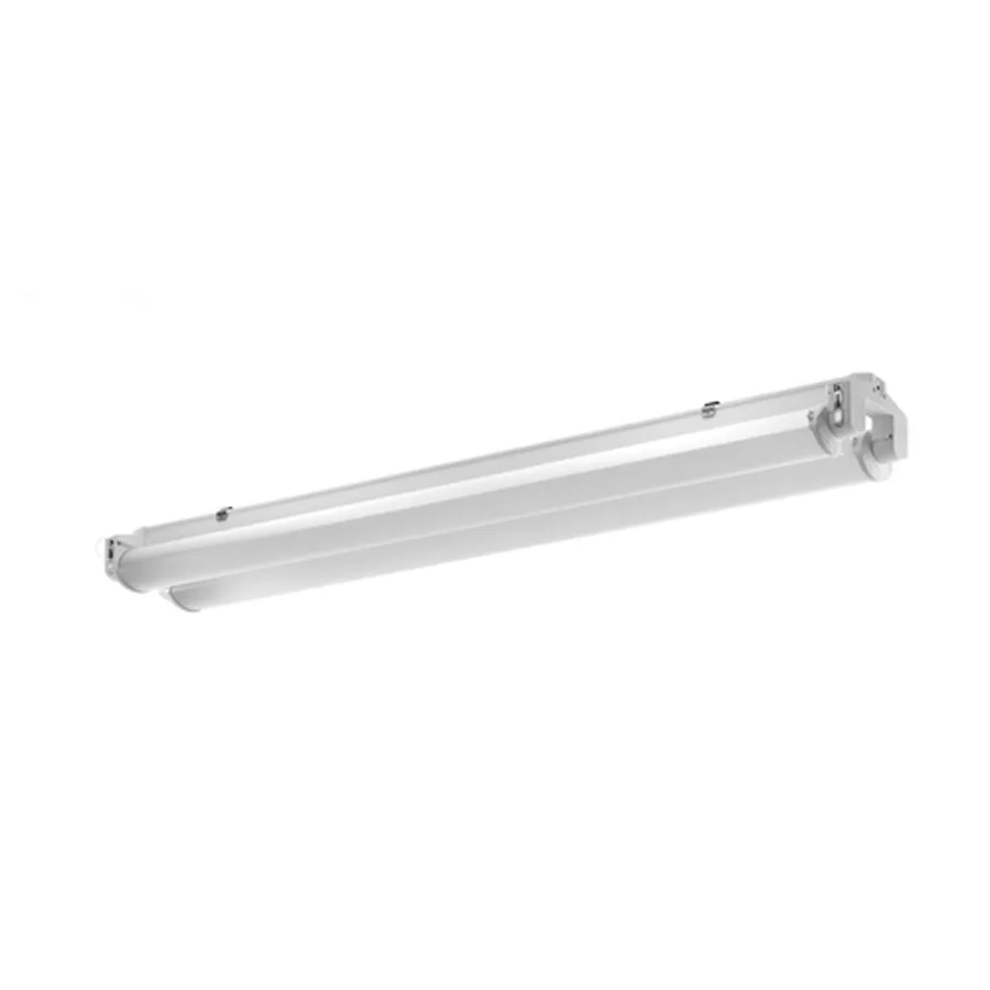
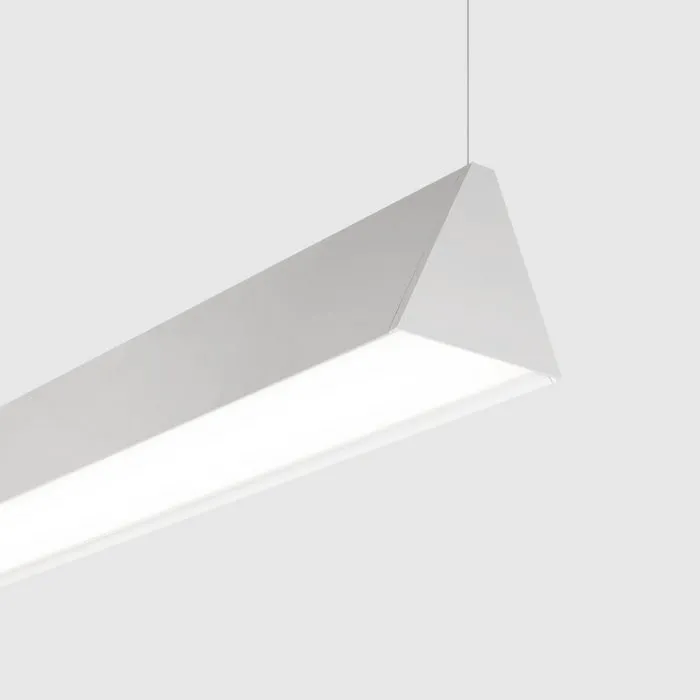
For a small room with a low ceiling, a surface-mounted linear light may be easier to place clear of access paths than a suspended fixture. In taller electrical rooms, selected high bay lights can provide the needed mounting height and service approach. Neither category is a blanket recommendation. Select the actual output, distribution, mounting, lens, controls, environmental rating, and access method for the room in question.
Design light for the task, not only for the room average
Map the visual tasks that occur at each equipment face: reading engraved labels and warning markings, identifying circuit numbers, using test equipment, servicing a disconnect, inspecting cable entries, and moving safely from the doorway to the work area. Include vertical equipment surfaces, not just a horizontal floor calculation. An average illuminance value can conceal a shadow at a switchboard face or bright reflection on a display.
OSHA specifically requires illumination for working spaces around indoor service equipment, switchboards, panelboards, and motor control centers. It allows an adjacent light source to provide that illumination, but the submittal and calculation should demonstrate that the installed arrangement actually lights the selected working spaces. OSHA 29 CFR 1910.303(g)(1)(v)
Ask the lighting designer to document the luminaire configuration used in the calculation: output package, optic or distribution, mounting height, equipment height, modeled workplanes, reflectances, obstructions, and maintenance assumptions. Review the result with the electrical engineer and facilities team at equipment elevations. If a product family has multiple outputs or lenses, name the exact selected configuration rather than relying on a brochure-level description.
Keep switching safe and manual control available
Controls need special treatment in electrical rooms. OSHA states that illumination in an electric-equipment room may not be controlled by automatic means only. Its requirements for higher-voltage work areas also address arranging outlets and control points so a person changing a lamp, repairing lighting, or turning on lights is not endangered by live or moving parts. OSHA 29 CFR 1910.303
That does not mean an electrical room can never use an occupancy sensor or a schedule. It means the design should maintain an appropriate manual means of obtaining working-space illumination and verify the final behavior with the project engineer and AHJ. Put the manual control location, sensor coverage, time delay, automatic behavior, override, and normal power circuiting on the controls narrative. Locate the switch where a person can use it without entering a hazardous position or relying on a sensor to detect them after a fault or service interruption.
DOE guidance describes occupancy sensors as a common building lighting control, but savings estimates vary by room type, operating pattern, installation, and commissioning. Treat an automatic control as a project-specific energy strategy, not as evidence that it is suitable for an electrical working area. DOE lighting-controls guidance
Specify construction and service access for the real environment
Electrical rooms are not all dry, clean interior closets. Record the actual environment: indoor or outdoor location, ambient temperature, humidity, dust, washdown exposure, corrosive atmosphere, vibration, ceiling construction, and whether the room is routinely occupied or locked. Then verify the selected fixture’s published environmental limitations, ingress marking where applicable, lens and gasket construction, mounting detail, listing, driver location, and maintenance instructions.
Avoid a generic note such as “industrial fixture” without identifying the selected configuration and its published suitability. A lens that resists routine dry dusting may not be appropriate for a wet process area; an elevated fixture may produce less glare but be impractical to service above energized equipment. Coordinate lamp or driver replacement with lockout procedures, access equipment, and the planned position of lifts or ladders. The lighting outlet and service plan should never create an additional electrical exposure.
Coordinate egress and emergency lighting as a separate system
General room lighting, exit signs, and emergency lighting have related but different purposes. Keep the exit path visible from the room door to the next safe route, and coordinate signs, doors, stored equipment, and future electrical additions so they do not obscure that path. OSHA requires each exit route to be adequately lighted so an employee with normal vision can see along it, and requires exit signs to remain visible. OSHA exit-route lighting and marking
Use the emergency and exit lighting schedule to document the selected unit or system, power source, test method, mounting condition, circuiting, and interface with normal, generator, inverter, or battery power. The adopted building and fire codes may impose further requirements beyond this workplace guidance, so coordinate the final system with the AHJ and the project’s life-safety drawings. Do not assume a normal-lighting occupancy sensor, a shared branch circuit, or an equipment-room door automatically establishes the emergency design.
Commission the installed room, not just the drawings
At turnover, inspect the room with panels and other equipment installed and accessible. Verify that the selected fixture locations leave the documented working spaces clear; that doors open as intended; and that labels, equipment faces, and access paths are readable under normal operation. Test manual controls, automatic functions if used, and restoration after a normal-power interruption. Test emergency and exit-lighting operation using the project’s approved procedure, then retain the results with the facilities closeout record.
The facilities package should include the luminaire schedule and cut sheets, controls narrative, circuiting or panel schedule, selected photometric calculation, emergency test record, cleaning and service instructions, and the final reflected-ceiling and equipment coordination drawings. This record gives the next electrician or facilities manager evidence of the intended configuration before a replacement fixture, ceiling change, or storage practice erodes safe access.
Electrical-room lighting submittal checklist
- A coordinated plan and elevation set showing equipment, panel-door swings, required working spaces, ceiling devices, cable trays, access panels, and service routes.
- A calculation that identifies selected luminaires and models the actual equipment faces, workplanes, obstructions, reflectances, mounting heights, and maintenance assumptions.
- Fixture documentation for the selected output, distribution, mounting, environmental limitations, listing, lens, driver access, and maintenance procedure.
- A controls narrative showing manual switching, any automatic function, override behavior, sensor coverage, time delay, and normal/emergency circuit relationships.
- Emergency and exit-lighting documentation stating the selected equipment, power source, test method, mounting, and final exit-path coordination.
- Commissioning records confirming clear working spaces, equipment-door operation, readable labels, normal controls, emergency operation, and facilities handover.